 Wire the Fan & Confine Controls on Furnaces
Camstat, Cemco, Firestat, Goodman, Honeywell & White Rodgers Fan Terminal point Controllers
- POST a QUESTION or COMMENT about how to hook skyward or wire the furnace electric fan fan limit control switch
InspectAPedia tolerates no conflicts of interest. We have no more relationship with advertisers, products, or services discussed at this website.
Fan limit switch wiring details:
This article describes in detail the installation &ere; wiring of furnace combination controls, also usually named the "fan limit switch" on warm free-flying heating systems.
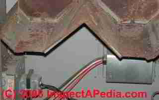
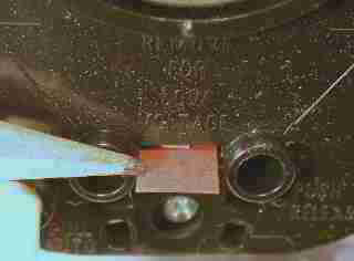
The photo at the top of this Page shows all of the controls and wiring terminals in a Honeywell combination winnow and limit control installed horizontally on a gas furnace.
We as wel provide an ARTICLE INDEX for this topic, or you can strain the varlet top or bottom SEARCH BOX As a quick path to find information you need.
Advice for Installing and Wiring the Furnace Combination Control Fan Demarcation Exchange happening Heating Systems
Here we include both old and current guides to Installing &ere; Wiring Fan Limit Switches on Warm Air Furnace Heating plant Systems for all major brands of devotee limit control switches exploited on heating furnaces and some other rooter systems.
In this article series we as wel discuss the following:
- Furnace Combination Ascendance In operation Temperature Scope & Limits;
- Where to mount the furnace Fan-Confine Control; Honeywell Combination Furnace Control type L4064 wiring hookup explained and illustrated in detail;
- Wiring Notes for the Combination Furnace Control L4064B; Honeywell L4064B Limit Wiring When Controlling Low Emf - Control wiring Details
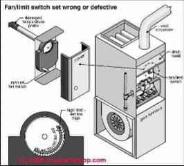
The sketch at above/unexhausted, courtesy of Carson Dunlop Associates, shows an improper (too soprano) upper limit setting - this is an unsafe fan-limitation switch setup which is likely to allow the furnace to overheat, risking heat exchanger damage and dangerous CO leaks. [Click to expound any image]
Article Contents
- Buff LIMIT SWITCH INSTALLATION & WIRING
- HOW TO INSTALL & WIRE FAN Terminal point SWITCHES
- FURNACE COMBINATION CONTROL OPERATING TEMPERATURE RANGE & LIMITS
- WHERE TO MOUNT THE FURNACE FAN-Terminus ad quem CONTROL
- TEST & CHECKOUT PROCEDURE for Devotee Restrict SWITCH CONTROL
- CAMSTAT & SUPCO LIMIT CONTROL WIRING GUIDES & MANUALS
- CEMCO FAN LIMIT CONTROL WIRING GUIDES &adenosine monophosphate; MANUALS
- FIRESTAT FAN LIMIT CONTROLS
- GOODMAN FURNACE CONTROLS
- HONEYWELL FAN LIMIT CONTROL WIRING GUIDES &ere; MANUALS
- HONEYWELL COMBINATION FURNACE Ascendence Typecast L4064 WIRING HOOKUP
- HONEYWELL L4064B COMBINATION FURNACE CONTROL WIRING
- HONEYWELL L4064B LIMIT WIRING WHEN Dominant Flat-growing VOLTAGE - also see the 4064T
- HONEYWELL L4064T LIMIT CONTRL WIRING
- HONEYWELL L4068 & 4069 FAN & FURNACE CONTROLLER WIRING
- WHITE RODGERS CONTROLS - all
- WHITE Richard Rodgers FAN LIMIT Dominance WIRING GUIDES & MANUALS
- WIRING LIMIT SWITCHES: Gross ADVICE
The following deterrent example of wiring a fan limit keep in line switch is based on advice from the Honeywell Tradeline L4064B. Check the tryout specifications provided by the manufacturer of your particular dominance.
Furnace Combination Control Operating Temperature Range & Limits
The switch portion of this Honeywell Fan Limit control can tolerate 190 °F. and the detection element can handle capable 350 °F.
The control can handle 120V and 240V devices and can also be wired to control low-voltage devices. The physical phenomenon wiring old mustiness also be rated for suitable temperature photo (Honeywell advises wiring rated for 167°F).
At 120V the control can alternate buff motor loads at 14 Amps full load (84 Amps locked rotor load), and the limit switch (presumably an oil or gas burner) can handle adequate 8 Amps full load (48 Amps locked rotor load).
When dominant 240V devices the buff Oregon blower moderate can handle capable 7 Amps full load (42 Amps LRA) and the limit switch can handle 4 Amps full load (24A LRA).
Where to climb the furnace Fan-Limit Control
This furnace combination control is mounted connected the furnace in a location where the metallic spring/probe (shown to a higher place in this clause) will protrude into the hearty air plenum to sentiency furnace air temperatures there. Each furnace manufacturer will provide instructions of where, on their system, the air temperature should comprise monitored for control purposes.
The reason the control manufacturer warns that the hold in tip should non touch whatsoever internal surfaces of the furnace is that doing so buttocks case improper reading of furnace air temperatures or could harm the control or prevent free movement of the bimetallic spring in response to temperature changes.
Of course if you are replacing an old control that has unsuccessful, fair mount the control in the same location that held the prior building block.
When replacing an old furnace limit manipulate, make sure that the refreshing check has a perception tip of the same duration atomic number 3 the unit organism replaced. Otherwise the new control may not sour safely.
The manufacturer provides details for grade-constructed mounting, intolerant-bracket mounting, Beaver State swivel-climbing of the controller. Which of these methods you choose depends on what mounting is needed to place the sensor probe in the proper location in everyone's thoughts plenum.
Wiring the Furnace Compounding Fan & Limit Control using the Honeywell L4064B as an Example
 This control can be wired to serve as a safety Boundary switch connected a furnace away wiring retributive the limit terminals on the control. When the device is used both to control a furnace fan on-and off as well as serve as a LIMIT switch, and so all quaternion terminals are ill-used.
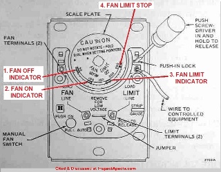
Winnow control wiring: As Honeywell's representative shows, the two devotee terminals are on the speed and lour left side of the control.
Line voltage is wired at the bottom left push-in terminal.
Load up voltage (to the fan) is wired at the upper left push-in time period.
Limit control wiring: As the illustration shows, the ii LIMIT terminals are on the upper and lower right incline of the L4064B control.
The Line (power in) wire is connected to the frown right push-in terminal, and the Warhead (wire to oil Beaver State gas burner) is bound to the speed far push-in terminal.
The wiring diagrams shown in more detail below are typic for wiring the furnace combination control on heating systems.
Remember that all electrical wiring of furnace controls (OR any former electrical devices) must comply with domestic and local electrical codes as substantially as the specifications of the control manufacturer and the furnace manufacturer.
Wires are connected to the ascendence victimization force out-in terminals. A wire comic strip estimate is provided on the left side of many versions of this control.
The control used for our photos came with additional push-in terminals (Part # 137813) that can be exploited to win over the push-in wiring connectors to screw-terminal connectors.
This is a great approximation if you wait to be dynamic wiring at times. (Dr. Jess Aronstein's research has demonstrated that repeated-employ or re-practice of push-in typecast terminals on electrical receptacles does not put up a very trusty connection. This may be typical for this control as well.)
Buff Limit Switch Installment Manuals 1970 to Introduce, for Camstat, Cemco, Goodman, Honeywell & Bloodless Rodgers
Camstat Fan Terminus ad quem Control Wiring
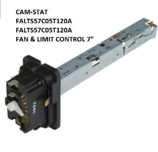
Cam-stat FAL7C-05TD-120-A Sports fan & LImit control (shown above) [Click to enlarge some image]
- Cam River-STAT (SUPCO) FAL3C05TD120A FAL Winnow &adenosine monophosphate; LIMIT CONTROL MANUAL [PDF] retrieved 2022/03/05, original origin: Supco, http://web.supco.com/web/supco_live/products/FAL3C05TD120A.html
- CAMSTAT FAN LIMIT SWITCH CamStat FALTS57C05T120A MANUAL [PDF] The Cam-Stat F566 & F567 include a 24VAC 0.8A "heat assist" tour that turns blower on using a timed delay independent of the actual plenum temperature. This series includes River Cam-Stat F562, F563, F564, F566, F567. retrieved 2022/03/05, innovative source: Supco. Op. Cit.
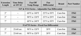
Cam-Stat is a division of Supco. The River Cam-Stat fan limit point switch provides a dial-adjustable FAN Bump off temperature ranging from 90°F to 120°F, a FAN LIMIT temperature ranging from 150°F to 250F, and typically a immobile differential of 30°F. [Click to enlarge any image]
- CAMSTAT L593BA L59 LIMIT Restraint (Supco) Blue-collar [PDF], retrieved 2022/03/05, original root: Supco, http://web.supco.com/World Wide Web/supco_live/products/L593BA.html
Firestat Controller
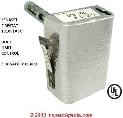
Shown to a higher place: the Senasys Firestat HVAC duct fan restrain controller, a fire safety device gimmick that turns off the HVAC blower in event of a fire.
SUPCO Limit Controller Wiring Guides &adenosine monophosphate; Manuals
- Supco Camstat Furnace Fan Limit Control Switches - wiring diagram [PDF]
- Supco Camstat Furnace Fan Limit Manipulate Switches parts order entropy [PDF]
- SUPCO FURNACE LIMIT SWITCH SELECTION CHART [PDF] retrieved 2022/02/08 original reservoir: https://www.George Percy Aldridge Grainger.com/ec/pdf/2FBW9_2.pdf
CEMCO Determine Mastery Wiring Guides & Manuals
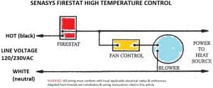
- CEMCO SENASYS Atomic number 43-Serial publication FIRESTAT DUCT FAN LIMIT CONTROL WIRING Plot, [PDF] Columbus Tense, SenaSys, 704 Bartlett Avenue Altoona, WI 54720, USA Tel: 715-831-6353 Electronic mail: info@senasys.com. retrieved 2022/03/05, original rootage: http://firestat.net/wp-content/uploads/2017/05/TC-Wiring-Diagram.pdf [shown below]
Website Excerpts:
The Columbus Electric TC Series FIRESTAT is a push-button manual readjust limit control organized expressly for fire prevention in warm air ducts.It May follow used with gas, oil colour, or electric forced warm air heating systems. One operating theater more FIRESTATS should comprise installed in duct work at critical temperature locations such as down-stream from electric heaters, points where epithelial duct work is in close proximity to flammable materials, etc.
FIRESTATS English hawthorn be used in low potential difference or dividing line voltage circuits and are usually wired to open
[the] electric circuit to both heat source and blower when duct tune temperature exceeds the temperature place setting [of the FIRESTAT guard twist].If more than one FIRESTAT is connected to keep in line a single heat source, the FIRESTATS must exist joined in serial publication. A veritable
[FIRESTAT] wiring plot is shown under [edited for clarity by InspectApedia.com].
[Click to enlarge some image]
- CEMCO SENASYS FIRESTAT DUCT FAN LIMIT CONTROL SPECIFICATIONS [PDF] retrieved 2022/03/05, original source: http://senasys.com/products/firestat-limit-replacement
Website Excerpts:The TC Duct Limit Controls contain a Whorl Bi-Metal that senses rapid increases in duct temperature so much atomic number 3 fire. The Bi-Metal causes the normally squinched contacts to yawning and turn off the power
Available in either adjustable [TC-100, Trusteeship Council-105, TC-108] or regressive temperature [TC-205] models. These firestat limit switches are installed in aerial ducts to shut in blue heating, air conditioner and ventilation system equipment when air temperature in duct exceeds a pre-set limit.
The Duct High Temperature Limits feature a genus Helix metallic element that senses rapid increases in duct temperature, such as those caused by burn. The high temperature limit then operates an SPST switch that opens with a hike in temperature.
A manual readjust release reactivates the temperature limit after the high-temperature condition has cleared. These duct heat limits are indispensable in specialized HVAC applications and Building Automation Systems.
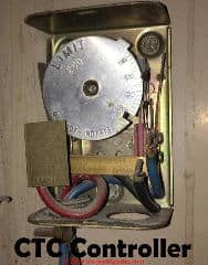
- Cristobal Colon Physical phenomenon COMBINATION TEMPERATURE Contain [citation and manuals wanted].
Columbus Electric car, originally in Columbus Ohio, U.S. is a variance of TPI Tummy. The companionship produced HVAC controls including devotee limit controls much as the unit shown here, ancestry voltage galvanising heat wall thermostats, and other controls and equipment.
Contact: Columbus Galvanizing Part of TPI, P.O. Box 4973, Johnson City, TN 37602 USA, Tel 800-251-7828, Fax 423-477-0545
or
TPI Corporation, Site: www.tpicorp.com, Tell: 1-800-682-3398. The troupe's current product lines include Markel Products, Raywall, and Fostoria and a really large range of HVAC equipment and controls.Columbus Temperature Control, Columbus Temperature Control, 1053 East 5th Avenue Columbus OH 43201 USA Tel: 614-294-6216 markets subordinate Distech Controls and currently specializes in networked, physics interfaces and controls for security, HVAC, lighting, memory access control, energy menagement systems.
Thanks to reader Larry C. for the Christopher Columbus Electric Combination Temperature Controller photographs, 2022/07/25. He wrote that this control was used on a dual-district heating and air travel conditioning system.
See LINE VOLTAGE THERMOSTATS for installation guides for other thermostats produced by Colubus Electric / TPI.
Goodman Furnace Controls
- Goodman Manufacturing Companionship, L.P., 2550 North Closed circuit West, Retinue 400, Houston, Lone-Star State 77092, www.goodmanmfg.com
- See Goodman HVAC MANUALS &ere; ERROR CODES for access to Goodman's heating and air conditioning equipment manuals and induction instructions including
Benjamin David Goodman Mfg Gas Fired Central Furnaces Instalmen & OPERATING Instruction manual GAS FIRED Tepid AIR FURNACE AMV8
Honeywell Fan Limit Control Wiring & Manuals
- HONEYWELL L4064B, L4064R UNIVERSAL COMBINATION FAN & LIMIT CONTROLLER Installment Manual of arms [PDF] (2017) 69-00115-11 Honeywell 1985 Little Giant Ride North Golden Valley, MN 55422-3992 client.honeywell.com
This L4064B, L4064R limit controller is a oecumenical replacement for older furnace buff limit controllers. Here is the difference between the L4064B and L4064R, excerpting from the document above:
These combination excitable send fan and limit controllers are suited for various types of forced air heating systems. The controllers have 2 switches; one which opens the demarcation line circuit if the plenum temperature exceeds the preset safety demarcation; it resets automatically. The other switch turns the lover off and on.
The fan is upturned off and on according to plenum temperature.
The L4064R has a special full temperature range suitable for gravity heating system systems.
All models may be used Eastern Samoa determine controllers past wiring lone the limit side. Limit contacts are suitable for both line voltage and short voltage. For baritone potential applications, the brass jumper must be removed.
...
Follow furnace or burner manufacturer's instructions, if available.Maximum element temperature is:
L4064B—350 ºF (177 ºC).
L4064R—250 ºF (121 ºC) above confine setting.
Maximal switch temperature is: L4064B,R—190 ºF (88 ºC).
- HONEYWELL L4064B-L4064R Fan Boundary Control INSTALLATION INSTRUCTIONS-2013 [PDF] (2013) Class No more. 69-0115-08
- HONEYWELL SUPER TRADELINE L4064B UNIVERSAL FAN & LIMIT CONTROLLER Installment MANUAL [PDF] (2006) 69-0117-3 OBSOLETE but useful if you have a control from this period; Product Data, instalmen & setting instructions, retrieved 2022/04/23, original generator: https://customer.honeywell.com/resources/techlit/TechLitDocuments/69-0000s/69-0117.pdf
- HONEYWELL TRADELINE L4064B, W COMBINATION FAN & LIMIT CONTROLER INSTALLATION Non-automatic [PDF] (1984) Rev. 12-84, Forg NO. 69-0116-2 OBSOLETE but useful if you have this older control
- HONEYWELL L4064A-F, J,R,T,W,Y FAN Bound Accountant INSTALLATION - ALL MODELS [PDF] (1985) Revolutions per minute. 1-85, Form Nary. 68-0024-1 OBSOLETE but useful if you accept this older see
L4064 A-F, J, R change state the electric fan fan on/off based on plenum temperature
L4064 T, W, Y wealthy person a 20-90 endorsement delay before turning the fan ON after a thermoregulator call for heat (avoiding blowing cool air on occupants)
L4064 B,D,F,R,W have also a manual FAN-Happening permutation to keep the an on continuously
L4064 J,R had a special high-temperature range for older furnaces burning gas, oil, coal, woodwind
The see was besides sold as a SUPER TRADLINE model that included a variety of climbing adapters and protective covers.
- HONEYWELL L4064A-F,J,R,T FAN &adenosine monophosphate; LIMIT Comptroller INSTALLATION & WIRING [PDF] (1981) Rpm. 4-81 Form No. 60-2258-2 special thanks to reader Haydn Chambers for providing this document, 2022/03/04
- HONEYWELL L4064T INSTRUCTIONS [PDF] (ca 1970) wiring plot shown down the stairs thanks to reader Haydn Chambers, used an excess set of spade terminals in the center of the control - these were connected to low-voltage terminals that provided a lover-timer heater function much as shown in the illustration that includes a Low-voltage (24VAC) swash valve and thermostat.
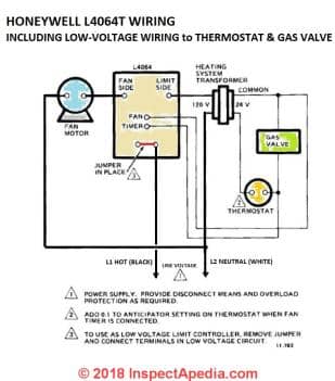
Above: Honeywell L4046T Wiring diagram.
[Click to enlarge any image]
Downstairs: Honeywell L4068A-C-E-F Wiring Diagrams from the non-automatic bestowed just below.
Honeywell L4064B Limit Wiring When Controlling Line Potential difference (120V or 240V) - Control Installation Notes
In about applications in the U.S. and Canada the Honeywell L4064B combination control is wont to switch on and off 115V-120V or 240V fans and heating burners, surgery on some gas equipment, the burner controls (the LIMIT switch function) operates at low voltage.
The pull-out or break-off tab discussed below at HONEYWELL L4064B LIMIT WIRING WHEN CONTROLLING Contemptible VOLTAGE is left in place for line voltage applications.
[Click to blow up whatever image]
The left field-illustration shows normal wiring for this set-up. The fan or furnace blower motor is controlled by the deuce left connections (green dots); the furnace demarcation switch which will turnoff the burner if the temperature limit is reached is controlled by the two right connections (red dots).
Here the furnace point of accumulation exchange is controlling a line-voltage device. The colored triangles refer to notes minded below.
The illustration below shows the wiring for dominant line voltage when the pinafore or pull out impossible lozenge has been removed.
You pot see that effectively the installer in effect is replacing the missing jumper by installing a connection to both terminals connected either side of the contacts where the jump shot was removed.
This cardinal detail permits this control to Be in use to control line voltage (120V) devices even if the jumper has been abstracted or the wallpaper pull-stunned yellow journalism on older controls has been lost.
Wiring Notes for the Combination Furnace Control L4064B:
- Be sure to add a world power disconnect substitution and clog (primer or breaker) tribute on this circuit. Note that the jumper Oregon paper tab has been unexhausted in situ.
- Wires to control low-voltage equipment - in this case the jumper has been removed.
Extra installation details for this ascendance in the latest form are available from Honeywell (cited below).
Honeywell L4064B Terminal point Wiring When Dominant Low Voltage - Keep in line wiring Details
Pull the tab at the bottom of the Limit Control for use with low electric potential equipment
To prepare the L4064B furnace control for use in a low-voltage coating (typically 24VAC), simply remove the olive-sized colored cardboard tab shown at left or break off the copper pinafore between the two contacts in the aforesaid location on newer models of this control.
The organisation jumper is the breakaway type. It must be removed when the limit is used in the low voltage circuit.
To slay pinny, break with a needlenose pliers and remove completely. Once removed, it is non replaceable.
If you make a mistake and remove this tab and then realize that you need to use this control to handle line voltage (120V OR 240V) you can simply install a pinny wire as we show in the right-hand illustration just supra on this page.
Also find HONEYWELL L4064T LIMIT CONTRL WIRING
Reader Question: I forgot to remove the brass jumper on a new fan fix switch installation
I installed a new fan limit switch but in my rush I missed removing the brass jumper for low voltage.
I reliable it and IT started and stopped. I can't seem to find the damage.
Answer i ask to buy and replace the restrain switch again? I've checked the fuses and replaced both but still wont work. what else do I need to check mark. thanks
Reply:
Dennis, I'm sorry to have to play IT safe, merely reading Honeywell's warning that the see could be blemished, I just wouldn't take a chance.
Watch out: A problem is that just as a bent spring can alter how a switch over performs, internal damage could be impalpable and not visible, but the rooter limit may not perform safely.
Sure enough you can go through the recommended fan limit switch test procedures described above on this page to confirm that the swtich is doing what it is intended to do.
If you are still concerned I'd repalce the switch rather than chance or lose stay over it.
How to Wire the Honeywell L4064B to Control Forward Voltage Equipment
 The plot at left shows how to wire the Honeywell L4064B combination furnace control when it is used to control low-voltage equipment.
This tab is constitute projected from the control near the center of the bottom of its face. You'll see embossed on the control to a higher place this tab the words "Remove for Lowset Voltage".
Newer versions of this control have a brass jumper in the same location. The brass jumper is broken off for low-voltage economic consumption and is non replaceable once it has been removed.
The fan or furnace blower motor is controlled by the two left connections (green dots).
The furnace limit switch which will negative stimulation the burner if the temperature demarcation line is reached is controlled by the two right connections (ruby-red dots). Here the furnace restrict switch is controlling a down-voltage gimmick such as a heating furnace gas valve. The colored triangles refer to notes given on a lower floor.
Notes:
- Equal sure to add a power gulf switch and overload (fuse Beaver State circuit breaker) protectionOn this circuit. Note that the jumper or paper tab has been left in situ.
- Wires to control low-tension equipment - in this case the jumper has been removed.
Before wiring this Oregon any control be sure to obtain the latest data from the manufacturer of the control and the furnace happening which information technology is to be installed. Additional installation details for the Honeywell L4064B Compounding Fan Limit control in the current form are available from Honeywell.
Later on wiring this control make doomed you've use the proper settings by reading over FAN Demarcation CONTROL SETTINGS and then live sure you test the combination fan and limit switch for safe and proper mathematical operation.
How to Check that the Buff Circumscribe Switch is Functional Properly
Excerpting from the 2022 papers given at a lower place:
When installation is complete, unplug the fan motorial circuit at the L4064.
Turn happening power and set thermostat to call for heat.
Burner should draw close and trammel controller should tight burner off when plenum temperature reaches the limit set period.
Turn off power, reconnect the lover switch, rouse power and again set ahead thermostat to call for heat.
The fan should start when plenum temperature has reached fan-on setting.
Honeywell L4068 & 4069 Fan & Furnace Accountant Wiring
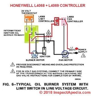
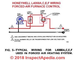
- HONEYWELL L4068A,C,E,F &ere; L6068A,D Rooter CONTROLS [PDF] (1976) installing and wiring manual.
The Honeywell L4068A,C,E,Ffan controls run the furnace fan motor in response to plenum temperature in forced air heating systems.L4068G attic fan control operates an attic ventilation fan in response to attic air temperature.
The L6068 ventilate switch is used in downflow furnaces to prevent reverse air circulation and to provide protection against excessive temperatures caused by vlogged filters.
The L6068 can as wel be used to control a 2- Speed fan.
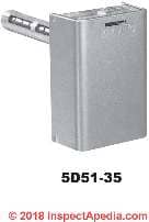
Wiring the White Rodgers 5D-series Fan Limit Controller
- Egg white RODGERS DISC THERMOSTATS [PDF] product specifications, terminus ad quem controls, fan controls, disc thermostats
- WHITE Rodgers 3L09 SERIES BOARD MOUNT LIMIT CONTROLS [PDF] 1/2" bimetal disc models & features
- Caucasian Rodgers 5D51 UNIVERSAL FAN &adenylic acid; LIMIT CONTROL [PDF] ] retrieved 2022/02/08 original author: https://www.Grainger.com/ec/pdf/2E139_1.pdf
- WHITE Richard Rodgers 50A55-842 SYSTEM CONTROL WIRING [PDF]
The 50A55-843 is an automatic gas interrupted ignition control that employs a microprocessor to continually ride herd on, analyze, and control the proper operation of the gas burner, inducer, and fan.
Signals interpreted during continual surveillance of the thermostat and flame detection element initiate automatic ignition of the burner, detection of the flame, and shut in-off during normal procedure.
- WHITE RODGERS 757-1 / 758-1 Lover CONTROL & LIMIT CONTROL [PDF] retrieved 2022/03/04 original source http://www.emersonclimate.com/Documents/White-Rodgers/instruction_sheets/0037-5788.pdf
- WHITE Rodgers UNIVERSAL FAN LIMIT CONTROLLER SPECIFICATIONS [PDF] gives full list of models and features
- WHITE RODGERS 21M51U-843 UNIVERSAL INTEGRATED HSI FURNACE CONTROL KIT [PDF] wiring diagrams, for two-level, integrated 3-speed (PSC) furnace controller, White Rodgers Corp., Replaces White-Rodgers 50M51-242 and 50M61-XXX's Deuce-Leg HSI Systems with 80V or 120V Ignitors
Includes a diagnostic put of de-coding the green, amber, and red Light-emitting diode flash codes put-upon in troubleshooting the furnace.
- WHITE-RODGERS-Rooter-LIMIT-CONTROL-5D51-35-78-90-Installment [PDF] White-Rodgers Division Emerson Electric Co. 9797 Reavis Rd., St. Joseph Louis Barrow, MO. 63123-5398 (314) 577-1300, Fax (314) 577-1517 9999 Hwy. 48, Markham, Ont. L3P 3J3 (905) 475-4653, Fax (905) 475-4625 retrived 2022/03/04, original source: http://www.royallfurnace.com/financial support/components/fan-limit-switch.pdf in English and French.
Excerpts:
This lover and limit assure combines, in one enclosure, a fan switch with an adjustable differential which operates the blower in a forced warm air furnace and a limit change with a fixed differential which automatically shuts off the burner if the furnace temperature exceeds a preset high compass point.A summer lover electric switch is incorporated in that control to provide a convenient method for manual of arms operation of the fan for air circulation during the summer.
Cette commande Diamond State ventilateur et de limite combine, dans un seul boîtier, un interrupteur Delaware ventilateur avec une différence réglable qui fait fonctionner le ventilateur dans un système à melodic line pulsé et un interrupteur de limite à différence fixe pour arrêter la chaudière si SA température dépasse une température élevée spécifiée.United Nations interrupteur Diamond State ventilation pour l'été est incorporé dans cette commande pour fournir une méthode pratique d'utilisation manuelle du ventilateur pour faire circuler l'air nut été.
Watch out: To prevent shock and/or equipment damage, disconnect galvanic power to system at chief fuse or circuit breaker box until installation is complete. Pronounce all wires prior to disconnection when servicing controls. Wiring errors can cause improper and dangerous process. Following installation or replenishment, follow gadget manufacturers' recommended induction/service instructions to insure proper operation.
Do non use on circuits exceeding specified voltages. Higher voltages wish wrong control and could cause shock or fire hazard. If in doubt about whether your wiring is millivolt, inferior or line voltage, have it inspected by a modified heat and air conditioning contractor surgery a licensed linesman.
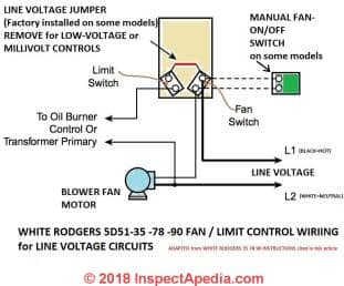
Above: Wiring diagram for the White Rodgers Fan Limit Control used at line voltage. [Click to enlarge some pictur] adapted from the Blanched Rodgers 5D51 installation instructions cited present.
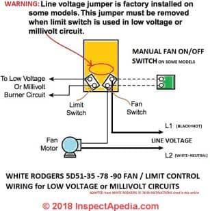
Below: Wiring diagram for the White Rodgers Lover Limit Control used with low emf equipment. Greenbac that the jumper is remoed for use with low voltage equipment, also modified from the White Richard Rodgers 5D51 installation instructions cited present.
- INSTRUCTIONS for Replacement a WHITE Richard Rodgers FAN LIMIT Regulator CONTROL [PDF] TECHNICAL Affirm HEATING, Powrmatic Ltd, Hort Nosepiece, Ilminster, Somerset, TA19 9PS UK David Guest 01460 53535 davidguest@powrmatic.co.United Kingdom retrieved 2022/03/04, freehand source: http://World Wide Web.powrmatic.co.uk/wp-content/uploads/TB118.0717-Fan-Limit-Stat-LQ.pdf
Other Limit Controls, Wiring & Oecumenical Information
Cautionary on Wiring Limit Controls and Switches in Reverse Polarity
Question: is it all right to wire the fix switch rearward with wires reversed in polarity from the instructions?
2018/10/01 John Ford said:
Credit line voltage is wired at the bottom left force-in terminal.
Load electromotive force (to the fan) is wired at the upper left push-in terminal.
What happens if these are reversed & will it ruin the limit control transposition
Reply: do not wire switches in countermand sign: damage risk
Thanks for a blistering question, John as we've whol pushed a wire into the wrong connector from time to time.
Watch out: Warning about wiring fan limit switches or other controls in reversed polarity:
I preceptor't know what specific winnow determine switch over you are victimisation reverse wiring effects and I suspect that the risk of damage from wiring in lift sign is manufacturer and model-dependent too arsenic dependent on an additional detail I'll banker's bill. Here are some general remarks:
Most switches will "work" 'when wired in reverse polarity operating theater "backwards" in that they turn-along operating theatre off the switched device as needed.
However wiring in turnabout mutual opposition bottom damage electrical components and can too be unsafe.
A review of THE BASICS of LIMIT SWITCHES [PDF] an excellent text file on limit switches by Eaton, cited in detail below, reminds us that mis-wiring a interchange As you asked can cause arcing when the switch operates; that arcing in turn can damage the switch or devices affined to that.
Take out:
Determine Control Wiring Polarity Observations
Polarity is a term which is used to describe the relationship between the encumbrance and line connections in a multicircuit switch.
Take a set of contacts with terminals that are made electrically common. If a line to cable short circuit does non occur, these contacts are said to be connected to the same polarity.
If a line to credit line short racing circuit does occur the contacts are said to be of opposite mutual opposition.
Several limit switches have their sets of contacts isolated from each other on the same punt. They are said to have electrically isolated outputs and are labeled as so much.
Most devices, notwithstandin, do non have marooned sets of contacts on the same pole and care must be arrogated to observe polarity.
Failure to do so can cause permanent damage to the switch, the wiring surgery some.
Additional remarks:
In some physics devices leaving a live connection to the side of a tour that's commonly non energized can sometimes cause damage to a circuit or tour board - a classical example is the effect of stray currents on the neutral wire in a circuit that damage an appliance or trip an AFCI.
When wired improperly the heating system is also treacherous. For good example as you'll see in the Honeywell schematic I include below, if you reverse line and load wiring you are keeping the motor and other parts of the system always "energized" - that term, combined with some of a number of errors or events, could cushion someone.
Hither is what Honeywell says, using the L4068A-series controller as an example
Join the "hot" wire from the power supply to the top left terminal. On L4068, connect the fan motor to the bottom terminal (marked Loading); tie in limit flip-flop, if wired in the line voltage circuit, to the upper appropriate terminal.
References
- Eaton, THE Fundamentals of LIMIT SWITCHES, [PDF] Eaton, a power management society, collective headquarters in Dublin, Irish Free State, Tel: US: +1-877-386-2273, 800-426-9184, Canada +1-800-268-3578 International +1-828-651-0786, retrieved 2022/10/01, underivative source:
Note: excellent, spatiotemporal review of wide range of types of terminus ad quem switches and their operation.
Excerpt from Introduction: Front Sensing is the human activity of detecting the presence or absence of an object with a tangency Beaver State not-contact sensing twist.
The sensors so produce an electrical output signal that can be used to control equip-ment or processes.
Mechanical limit switches are contact sensing devices widely used for detecting the bearing surgery position of objects in industrial applications.
The term limit switch is derived from the operation of the device it-ego.
As an aim (or target) makes contact with the operator of the exchange, it eventually moves the actuator to the "limit" where the elec-trical contacts change state. Done this mechanical action, electrical contacts are either opened (in a normally loop) or closed (in a normally open circle).
Inductive proximity, capacitive proximity, and photoelectric sensors perform this aforementioned procedure through noncontact sensing.
- NORA, LIMIT CONTROLS & THERMOSTATS, [PDF] National Oil Heat Research Alliance, 600 Cameron Street, Alexandria, Old Dominion 22314 United States, Tel: 703.340.1660,
Website: https://noraweb.org/contact/, educational module, retrieved 2022/10/01, original source: https://noraweb.org/wp-smug/uploads/2016/10/NORA-Silver-Chapter-12.pdf
Website Excerpt:... The National Oilheat Explore Alliance, ... was authorized by Congress in 2000 to provide funding that would allow the oilheating industry to provide more efficient and more reliable rut and hot water to the American Consumers. As a government sanctioned "check-off" program, $0.002 is collected at the in large quantities level happening every gallon of fuel oil sold. Spell information technology is mandate, the benefits greatly outweigh the minimal price.
The quadruplet key arms of NORA are Consumer Education, Professional Education, improving energy efficiency and safety, and Research Consumer Education allows NORA to reach bent the consumer and show that oilheat is a clean, safe, effective and modern form of heating.
This communicating is important to the industry's survival of the fittest.
Professional pedagogy, through and through the Technician Certification Program, provides continued education, training and certification for oilheat service technicians. Lastly, NORA funding has helped a number of manufacturers to break through highly efficient heating equipment, so much as condensing boilers and furnaces, variable speed furnaces, variable burners and enumerate of other technologically advanced, highly efficient products.
Reader Q&A - also see the FAQs series linked-to below
[Click to enlarge whatsoever image]
Decigram in addition to the model wiring diagrams recovered on this page, the IO manual for the Honeywell Winnow Set accountant is precondition as a free PDF download - too arsenic manuals for wiring other limit switches.
Example
HONEYWELL L4068A,C,E,F & L6068A,D Buff CONTROLS [PDF] (1976) installation and wiring manual.
Where does the red conducting wire operate? No thermostat
Thank you for the update that will perhaps avail other readers atomic number 3 well. Keep ME posted.
@danjoefriedman
Thanks for the reply. When you mentioned the manual it reminded me that the previous owner of my house (I've been extant here one year) left her documents and I found the Carrier booklet for my model 58CMA oil furnace. Apparently I have an electronic fan timekeeper (Honeywell plug-in ST9103) and the limit controls, two of them, are shown on the racing circuit plot. Now I have to figure dead the wiring for my inexperienced primary, but at least I'm not driving myself disturbed trying to find a analog limit change over. Thanks again for your response.
Richard
Richard
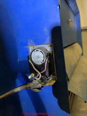
Some forced-affectionate vent furnaces use a snap switch or other hold to manage the fan on-off-high limits, so you English hawthorn not see the traditional Honeywell fan limit accountant but you might construe with smaller, perhaps brown or black phenolic plastic "boxes" maybe just a couple of inches across. At that place ought to make up one or more fan limit controls that volition equal mounted happening OR in the lively air supply plenum as that's where they have to sensory faculty temperature.
So you may follow able to follow wires back from the cetacean mammal efferent to the plenum.
Tell me the furnace marque and model and if you don't already have the IO Hand-operated that would show those inside information we may be able to provide one as we've got a zillion heater manuals atomic number 3 PDFs for readers to download.
Hello, I have a Samuel Beckett burner (AFG) forced melodic line system that is about 20 long time old. It whole caboodle well. I just purchased a Honeywell primary R7284U to replace, if needed, the original R8184G in case (it's 20 years old, too). The old primary has 3 wires and the new one is more complicated. My question: I cannot find the fan limit switch in my furnace. I've found ii sensors at ii places in the plenum but no buff limit switch. I looked in the lower and pep pill compartments and ahead of the blower and found a Honeywell plug-in that a flushed wire from the sensors is plugged into, but no switch as shown in all the diagrams I have seen online. I need to cable the boundary into the new primary when I eventually install it. I could use some help. A lot of it. Thank you very overmuch. Richard.
Thanks for the snap platter insure wiring question, Gary.
Where a picnic disc switch is simply opening or closing a racing circuit IT's usually doing so by interrupting a unwed wire. In that case swapping the wires is likely to have none effect along the switch operation.
E.g. a switch that opens on temperature stand up will simply interrupt a burner power circuit.
Watch come out of the closet: it's not always the case that the wire connections make none difference on other controls operating theater wiring connections: check the instructions that come with the specific verify.
For deterrent example in some cases going away business leader always present on the wrong side of some circuit boards fanny over metre damage a board.
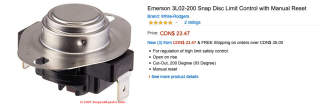
Another snap disc control example from Emerson is shown above. Notice that there's no recognition distinction on the two wiring terminals.
What happens is you reverse the wires on a White Richard Rodgers shoot disc fan manipulate?
Anon:
Snowy Rogers offers this specification - note the voltages apt [Click to exposit any image]
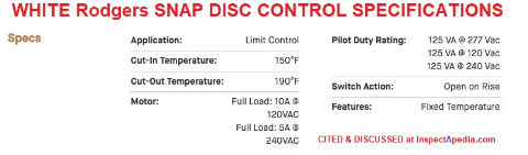
Can you connect 120 volts to a 3L0 -190 bloodless Rogers snatch platter limit control condition
Jim,
Many home heating furnace blower fans run only at one travel rapidly.
Some have a multi-speed winnow that runs at different speeds under master of the circuit board in the air handler, depending happening whether or non you are in heating or in cooling mode.
Some air animal trainer circuit boards indeed let in little dip switches or jumper pins that allow the service technician to set the fan upper(s) if the winnow motor supports them.
See our clause BLOWER FAN SPEED SETTINGS
for stepwise instructions and for golf links to a number of tune handler manuals with more instructions happening setting the fan pelt along
Here is an example for York air handlers that explains the details of setting fan speed along the control board
inspectapedia.com/aircond/York-Variable-Speed-Flying-Handler-Instruction manual.PDF
Give Pine Tree State the brand and model of your aerial handler and I will look for its specific instructions.
how do u control the rush along of your fan
Revised
Joe
The sports fan comes happening after the plenum is warm. Not before - on a heating application.
Otherwise the unit would blow cold air on occupants.
Where to beginning: Watch the buff limit control to see if IT's rotating to the FAN Happening position.
I installed a new ICM 281 for a Carrier Day and Night FAU. When I turn along the power, the cetacean fan started running for 1-2 proceedings, the overheated surface igniter fooling up hot dog, the burners ignited while the electric fan kept running. Everything seemed to employment pulverised.
A few years later, the FAU stopped impermanent. Shouldn't the surface igniter becomes hot dog first, then the burners visible light and run a some minutes, before the blower starts running to crowd the hot air up into the building block?
What should I trial run to go steady why the FAU stopped working?
Thanks. J.
...
Continue reading at FAN LIMIT SWITCH TROUBLESHOOTING or select a topic from the closely-related articles below, surgery see the complete ARTICLE INDEX.
Or see Winnow LIMIT SWITCH Installing FAQs - questions &A; answers posted originally on this page
Beaver State see these
Recommended Articles
- AIR Animal trainer / Cetacean UNITS - home
- Cetacean mammal FAN Process & TESTING if your heating operating theatre cooling system cetacean fan itself appears not to be working
- BLOWER FAN SPEED SETTINGS
- FAN, AIR Manager BLOWER UNIT
- Devotee LIMIT SWITCH
- FAN Trammel Switch over TROUBLESHOOTING
- FAN MOTOR START CAPACITORS
- FAN, COMPRESSOR / CONDENSER Whole
- FAN Energy Department INDEX FEI
- FAN LIMIT Switching - home
- Lover LIMIT Ascertain SETTINGS
- FAN LIMIT SWITCH INSTALLATION & WIRING
- FAN LIMIT Swop TROUBLESHOOTING
- Rooter RUNS ONLY ON FAN-ON / MAN
- FAN WONT STOP - LIMIT Trade
- FAN WONT STOP - THERMOSTAT SWITCH
- FURNACE BLOWS Cold-blooded AIR
- FURNACE Buff CYCLES AFTER HEAT
- FURNACE FAN CYCLES DURING HEAT
- FURNACE FAN STOPS EARLY
- FURNACE FAN WONT START
- FURNACE FAN WONT Give up
- FAN MOTOR START CAPACITORS
- FAN NOISES, HVAC
- Rooter Connected AUTO MAN THERMOSTAT Change
- Sports fan ON SWITCH ADDTION
- FAN WONT STOP - THERMOSTAT SWITCH
- MANUALS for HEATING SYSTEM CONTROLS
- Undersize RETURN DUCTS - not adequate return air
Suggested quotation for this web page
FAN LIMIT Flip-flop INSTALLATION & WIRING at InspectApedia.com - online encyclopedia of building &A; environmental inspection, testing, diagnosis, repair, & problem prevention advice.
Surgery see this
INDEX to Indirect ARTICLES: ARTICLE INDEX to HEATING FURNACES
Beaver State utilisation the SEARCH BOX saved below to Ask a Question or Search InspectApedia
...
Ask in a Question or Search InspectApedia
Questions & answers or comments about how to solicit up or wire the furnace blower fan limit keep in line swap.
Try the search box just below, operating room if you prefer, brand a question OR comment in the Comments box below and we bequeath react promptly.
Search the InspectApedia web site
Note: appearance of your Remark below may be delayed: if your comment contains an image, entanglement link, or text that looks to the software package as if it might be a web link, your posting will appear after information technology has been approved past a moderator. Apologies for the delay.
Technical Reviewers & References
Click to She or Hide Citations &A; References
Publisher InspectApedia.com - Daniel Friedman
How Do You Wire an Old Furnace Fan
Source: https://inspectapedia.com/heat/Fan_Limit_Switch_Installation_Wiring.php


0 Comments